


Sheet metal tolerances are mainly the variation of rolled sheet stock that can take place during the fabrication of metal. Accuracy is essential in sheet metal fabrication. However, tight tolerances are not easy to achieve as undesirable results can cause low-quality products and high delivery times.
Manufacturers need to achieve consistent results to have better control over tolerances according to the design needs. ProlenTech, among other companies, strictly consider the material properties and manufacturing processes, with consideration of design, and follows industry standards.
In this article, we will discuss all you need to know about sheet metal tolerances in sheet metal fabrication.
Sheet Metal Tolerances
Sheet metal tolerances can be defined as the differences from the specified range in which design dimensions of a part can vary. This variation shows the difference between the intended and actual dimensions of design. The upper and lower acceptable range for these variations is referred to as the manufacturing tolerance range.
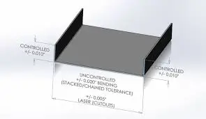 The typical range of tolerances for sheet manufacturing is from ±0.005″ to ±0.060”. However, sheet metal bending tolerances range from ±0.5 degrees to ±1 degree. And the bend length is ±0.010″ or 0.25mm, depending on sheet metal thickness.
Types of Tolerances
Let’s go through the list of generally specified sheet metal tolerance types.
Dimensional Tolerances
Dimensional tolerances are considered the basic specifications in sheet metal fabrication. Linear dimensions and angular dimensions are included in these tolerances. They reduce the risk of rejection by perfectly fitting and functioning during assembly as intended.
Geometric Tolerances
Form and positional tolerances come under geometric tolerances. Form tolerances deal with the straight surfaces and circular sheet metal parts. Positional tolerances properly align holes or slots at the right place during assembly.
Material Tolerances
The properties of the material, such as thickness and characteristics, directly impact sheet metal fabrication. The thicker the material, the looser the tolerances. The thinner material requires strict control.
Tolerances for Specific Materials
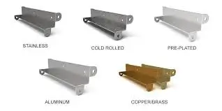
Different materials determine the performance and accuracy of the component, depending on their properties. So, there are different tolerance requirements for different materials. These materials are used to achieve the required tolerance through precision sheet metal fabrication.
- Aluminum allows for moderate tolerances due to its ease of forming.
- Stainless steel requires tight tolerances to maintain precision sheet metal fabrication because of its low ductility.
- Carbon is formable and strong. It permits moderate tolerances.
- Copper alloys also allow for moderate tolerances. It is known for exceptional thermal and electrical conductivity.
- Tool steel alloy requires tight tolerances due to its low ductility.
- Titanium requires strict tolerance control due to its strength-to-weight ratio and low ductility.
 The table below guides the general tolerance range with specific alloy examples for different materials:
| Materials | General tolerance range | Specific alloy example | Alloy Tolerances |
| Aluminum Alloy Tolerances | ±0.1 mm | 6061-T6 | ±0.010 in to ±0.030 in |
| Stainless Steel Tolerances | ±0.005 in to ±0.015 in | 304 stainless steel | ±0.005 in to ±0.015 in |
| Carbon Steel Tolerances | ±0.015 in to ±0.045 in | 1018 low-carbon steel | ±0.015 in to ±0.045 in |
| Copper Alloy Tolerances | ±0.008 in to ±0.020 in | C11000 copper | ±0.008 in to ±0.020 in |
| Tool Steel Tolerances | ±0.002 in to ±0.010 in | D2 tool steel | ±0.002 in to ±0.010 in |
| Titanium Tolerances | ±0.005 inches to ±0.015 in | Grade 5 Titanium Alloy | ±0.005 in to ±0.015 in |
Factors Affecting Sheet Metal Parts Tolerances
Knowing the factors affecting sheet metal tolerances is important to achieve consistent and accurate results. These factors determine the sheet metal tolerances during the production process.
The Material Thickness
The material thickness determines the tolerances. The thinner materials allow tight tolerances, while the thicker ones require loose tolerances.
Below are the common reference ranges for sheet metal thickness tolerances:
| Material Thickness (mm) | Tolerance Range (mm) |
| 0.5 – 1.0 | ±0.1 |
| 1.0 – 2.0 | ±0.15 |
| 2.0 – 3.0 | ±0.2 |
| 3.0 – 5.0 | ±0.25 |
| 5.0 – 8.0 | ±0.3 |
The Fabricating Techniques
There is a built-in tolerance limit for different manufacturing processes. The production stays economical and smooth if the tolerance is according to your allowable amount of variation. Hence, using cutting-edge technology like the CNC press break can achieve tight tolerances without compromising cost and quality.
Die and Tool Quality
The quality of the tool and high-end carbide die can cause consistent results. A good-condition tool can produce a component with tight tolerances. Similarly, a high-end carbide die can create a more precise component by keeping the tolerances up to 5 times longer.
 The Machine Capabilities
The precise and exceptional accuracy with tolerances up to ±0.001″ inches is achievable with the use of advanced machining techniques. But the regular maintenance of the machines is crucial to get this level of precision.
The Complexity of Design
The complexity of the design involves difficult cuts and bends. The simpler the part geometry, the easier it is to achieve accurate tolerances. The complex geometries allow for ±0.030” inches of tight tolerances
The Capabilities of Fabricating Company
The capabilities of an experienced manufacturer must include the advanced technology they are using and their skilled experts. Certified companies, such as ISO 9001, can maintain tolerances within ±0.005” for significant dimensions.
Typical Metric Manufacturing Tolerances for Sheet Metal Fabrication
There are some typical metric manufacturing tolerances that you need to know for precision sheet metal fabrication. These tolerances guide how or when to apply specific standards by ISO 2768, ISO 286, and (GD&T). These tolerances ensure quality sheet metal parts in the production process. The general tolerances also maintain a good balance between accuracy and cost-effectiveness.
Here is a detailed table related to the typical metric manufacturing tolerances:
| Process | Type | Tolerance Value |
| Laser Cutting | Linear dimensions | ±0.1mm for parts up to 1000mm |
| Hole diameter < 5mm | ±0.05mm | |
| Hole diameter > 5m | ±0.1mm | |
| Punching | Linear dimensions | ±0.2mm for parts up to 1000mm |
| Hole diameter | ±0.1mm | |
| Bending | Angular tolerance | ±0.5° |
| Linear dimensions | ±0.3mm for bends up to 1000mm | |
| Stamping | Linear dimensions | ±0.2mm for parts up to 100mm |
| ±0.3mm for parts 100-500mm | ||
| Welding | Linear dimensions | ±0.5mm for weld lengths up to 100mm |
| ±1.0mm for weld lengths 100-500mm | ||
| Forming | Linear dimensions | ±0.5mm for formed features up to 100mm |
| ±0.8mm for formed features 100-500mm |
Precision sheet metal fabrication manufacturers have standards like ISO 2768 for general tolerances and ASME Y14.5 for dimensioning and tolerancing. These industry standards are applied in aerospace and automotive for reliable sheet metal parts. Certified companies like ProleanTech follow guidelines and standards to guarantee consistency and quality.
Conclusion
Sheet metal tolerances play a crucial role in the fabrication of sheet metal parts to get consistent results. Different types of tolerances ensure the proper functionality of the part according to its intended design. Sheet metal tolerances have different dimensional variations depending on the thickness and characteristics of various materials. However, there are many factors that affect the functionality of the sheet metal parts.


")