A machine fits on the plan. Its cabinet sits inside the allocated rectangle, the operator has a place to stand, and the layout looks resolved. Then a service panel opens into a wall, a replacement assembly cannot clear the ceiling, or a trolley blocks the route to the door. The footprint was correct. The room was designed around too little information.
Early coordination with a system integrator Singapore architects can consult about production equipment should establish more than length and width. Installation, operation, and servicing place different demands on the building. Drawing those demands separately reveals where a compact arrangement depends on space that has already been assigned to something else.
Begin With the Route Into the Building
The first spatial test happens before production starts. Follow the proposed delivery route from the unloading point to the final machine position. Door openings, changes in level, corners, and overhead obstructions can matter as much as the destination room. A generous final bay does not solve a narrow turn outside it. The delivery configuration therefore belongs in the coordination information.
Ask which parts of the equipment arrive assembled and which can be installed separately. Do not assume a machine can be divided simply because its drawing contains several modules. Transport arrangements, lifting points, and reassembly requirements need confirmation from the equipment team. The architect can then coordinate the route against the actual delivery plan instead of an optimistic rectangular outline.
A useful layout review traces the route in both directions. Equipment may eventually need removal, and a large replacement component may follow much of the same path. A temporary opening used during construction can become inaccessible after the building is occupied. If future access relies on removing a partition or another installation, that dependency should be visible before the design is finalized.
Draw the Space Used During Ordinary Production
The operating envelope includes the movements that happen around the equipment. Incoming containers may wait beside a loading point. Finished work may leave on a trolley. An operator may need to reach a control or inspect a part without stepping into the material route. These activities cannot all occupy the same patch of floor simply because they occur at different moments in a drawing review.
Walk through one plausible replenishment sequence with the operations team. Where does the full trolley wait while the empty one is removed? Does an open door narrow a shared route? Can someone pass without moving stored material? These questions convert broad promises of sufficient space into specific arrangements that can be examined on the plan.
Motionwell Automation combines mechanical design with electrical and control integration. Bring both sides into the layout review. Establish where an operator normally works and which access points are used only under a defined service condition. The architect should not have to infer those distinctions from cabinet geometry.
Reserve a Separate Envelope for Service Work
A machine may be operable from the front and serviceable from several sides. Its service envelope needs to show panel swings, removable assemblies, access to connections, and the space required to handle removed parts. Merely drawing a person beside the cabinet misses the practical problem of where a cover or component goes after it has been detached.
Show Panel Movement and Component Removal Paths
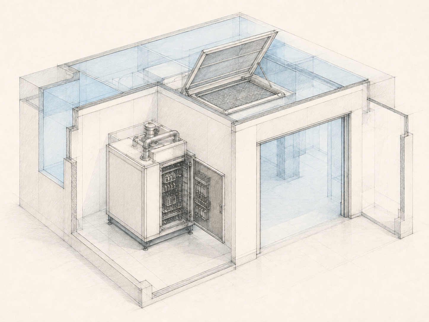
For a hypothetical inspection module, a side panel might open into an otherwise convenient storage recess. That recess cannot be treated as permanent storage if routine access depends on keeping it empty. Draw the panel in its open position and show the path of the largest regularly removed item. The resulting conflict is easier to resolve during layout design than after shelving is installed.
Medical-device equipment from Motionwell Automation can include cleanroom-oriented layouts and airflow considerations. For an architect, this makes access a coordination issue involving both the equipment and the room. Where service access from an adjacent area is feasible, the team should examine it; where it is not, the room must accommodate the agreed service activities.
Check Vertical Access in Section as Well
Plan views can conceal a service problem above the machine. A ceiling grid, duct, light fitting, or cable route may occupy the space needed to lift out an assembly or reach equipment mounted overhead. Add a section through the relevant area, with the intended removal movement shown. The required clearance must come from the equipment design, not a standard gap copied from another room.
Equipment and building-services teams may both have allocated the same overhead zone. Record who owns the interface and which drawing confirms the arrangement. Otherwise, a conflict visible in section can survive several rounds of apparently complete plans.
 Coordinate Room Performance Without Assuming It From Appearance
A clean-looking production room is not evidence that its environmental requirements have been met. Room airflow, equipment arrangement, materials, and the production process need coordinated review by the appropriate specialists. A translucent volume on an architectural diagram can communicate an intended zone, but it cannot establish actual airflow behavior or demonstrate qualification.
Motionwell Automation’s cleanroom guidance discusses equipment-related access and airflow concerns. Architects can use those concerns to structure questions about obstructions, service locations, and interfaces with building systems. The project team still needs to define its own requirements and determine how they will be verified. Avoid turning a supplier’s general cleanroom capability into a claim about a completed room’s performance.
Utility connections deserve the same attention. A connection point drawn neatly behind equipment may be awkward to reach after installation. Confirm the route, access arrangement, and responsible party for each interface before the surrounding space is closed in. Where the final connection detail is pending, mark the dependency so the area is not prematurely treated as resolved.
Review the Room as a Sequence of Uses
Before freezing the layout, review delivery, normal production, replenishment, and service as separate scenes. Each scene reveals different spatial demands. The team can then decide which areas may be shared at different times and which must remain available. Shared space is a deliberate operating arrangement, not spare capacity to be claimed independently by every discipline.
Include adjacent equipment in the service scene. Two machines may each have adequate access when considered alone, yet depend on the same clear area when panels are opened. If the plan assumes only one will be serviced at a time, operations must understand and accept that constraint. If it cannot be accepted, revise the layout. Leaving the overlap unexplained simply transfers an architectural decision to the person trying to perform the work later.
Keep the agreed access zones visible on subsequent fit-out drawings. Otherwise, a later storage addition can erase a carefully resolved clearance.
The final coordination drawing should make those choices readable. Keep the machine footprint, operating area, and service access distinct, and resolve major vertical constraints in section. A room designed this way may still be compact. Its efficiency comes from understanding how the space will be used, rather than from drawing the smallest possible rectangle around the equipment.