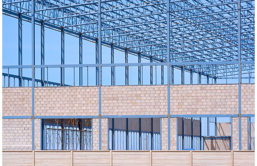
The facade of a pre-engineered metal building has to be settled before the frame is engineered, because brick, block, glass and stucco each need different stiffness, support and openings from the steel. The default wall on a metal building system is metal panels fixed to cold-formed girts, and the frame is designed to move the way that wall can. Change the wall, and the frame’s brief changes with it.
Pairing a steel frame with a masonry face is not new. The Wainwright Building wrapped its frame in sandstone, brick and terra cotta in 1891. What differs on a pre-engineered building is how the design is split. One engineer designs the frame, another designs the walls, and the facade only works if each knows what the other assumed.
Masonry walls and the open wall condition
An open wall condition is how a full masonry wall goes onto a pre-engineered frame. On that wall the manufacturer omits the girts and panels, and the masonry itself encloses the building. A frame can be designed with open wall conditions for any masonry attachment, tilt-up concrete included, but the manufacturer’s engineer has to know what each open wall will become. A wall that stays open and a wall waiting for reinforced block are different design cases.
The manual Concrete Masonry Walls for Metal Building Systems, produced in 2011 by the National Concrete Masonry Association with MBMA and the International Code Council, sets the ground rules for that handoff. Its standard case is a reinforced wall spanning vertically from the floor to a steel spandrel near the top, which carries the wall’s wind load back to the frames. Walls that span sideways between columns are treated as nonstandard, and that choice has to reach the metal building manufacturer in time for bidding.
The manual also divides the work. The manufacturer normally designs the rigid frames, endwall framing, roof system, girts, flange braces, canopies and fascias, plus any wind bracing other than the masonry. The masonry engineer designs the walls and the anchors that tie them to the steel. If the masonry is meant to act as a shear wall, the manufacturer shows the shear reactions on its drawings. If no reactions appear, the steel carries the lateral load on its own.
Letting steel and masonry move differently
A metal building frame is designed to far looser deflection limits than masonry normally accepts. The manual treats that gap, with shrinkage and thermal movement, as the core of the connection design. Citing AISC Design Guide 3, it gives a suggested lateral drift limit of H/100 under a 10-year wind for low-rise buildings with vertically reinforced exterior masonry walls. That target belongs in the order documents before the frame is sized, not after.
The details that absorb the remaining movement are architectural decisions too:
- Control joints at the column lines, offset at least 8 inches from the column centerline when the bay spacing does not suit the block.
- Bay spacing in even numbers of feet, which keeps the column lines on the 8-inch module of a concrete masonry unit.
- Slotted holes or flexible anchors where a wall must not pick up load in its own plane.
- Through-wall flashing at the floor line, which works as a hinge so the wall can rotate at its base as the frame drifts.
Brick veneer and stucco need a backup wall
Brick veneer is a skin, not a structure, so the first facade question is what it is tied back to. The masonry manual covers reinforced block with or without a veneer face, the familiar two-wythe wall. The other common backup is cold-formed steel framing, and the Brick Industry Association revised its Technical Note 28B for that assembly in April 2025. As STRUCTURE magazine reported, the note keeps L/600 as the established deflection limit for the framing but now lets designers use limits between L/360 and L/600 where the project justifies it.
Either way, the backup is a separate design decision from the metal building’s girts. If the brick is to be tied to the building’s own girts, those girts have to be designed for that stiffness, and the order documents need to say so. Portland cement stucco raises the same question, since a rigid plaster finish cracks when its backup flexes too far. Metal wall panels are the facade the girt system is designed around by default, and anything heavier or more brittle needs its backup defined before the frame is detailed.
Storefronts, canopies and signs
Storefront glazing sits in framed openings, and the header over a long storefront is a structural member like any other. Its deflection has to suit the glazing system, whose limits come from the glazing manufacturer, so the architect passes them on with the opening sizes. The masonry manual’s details include a steel spandrel serving as the head of a window at the top of a masonry wall. Doors, framed openings and open walls should all be checked on the manufacturer’s drawings before sign-off, because the frame is fabricated to what those drawings show.
Canopies and fascias normally sit in the manufacturer’s scope, so their loads are part of the frame design. Signs are a different matter. A large sign on a parapet or fascia adds weight and wind area, and it only gets designed for if someone states it.
Parapets and false fronts on a low-slope roof
A parapet or false front is a common way to give a metal building a flat-topped street elevation while the roof behind it stays at a low slope. In masonry, the parapet is the part of the wall above the spandrel, and the manual recommends setting the spandrel as high as the frame allows. Placing it above the rigid frame is difficult and not recommended. The manual’s guidance limits the masonry cantilever above the spandrel, parapet included, to a third of the wall’s span below it.
A parapet also changes how the roof sheds water and snow. Under 2024 IBC Section 1502.2, where roof drains are required and the perimeter construction would trap water if the primary drains back up, secondary emergency overflow drains or scuppers must be provided. ASCE 7 also sets drift loads at parapet walls, so the roof framing along that edge may have to carry more snow than the rest of the roof. Both belong in the brief when the elevation is drawn, not after the roof is designed.
Who decides what
The architect owns the facade: the materials, the wall sections and the serviceability criteria each wall needs. The design of the masonry or veneer, and of its anchors, stays with the architect’s engineer or the engineer of record. Manufacturers of commercial metal buildings design the frame and its secondary framing to those criteria, and show the reactions and bracing the wall designer needs. When the criteria arrive late, the frame is designed to whatever was assumed, and the facade has to adapt to the frame rather than the other way around.
The practical step is to draw the wall section before the metal building is ordered. A section through each facade type, showing the backup, the spandrel or girt it ties to, the parapet and the base flashing, tells the manufacturer’s engineer what the frame must do. It also tells the wall designer what the frame will do in return, which is the conversation the two engineers rarely have on their own.