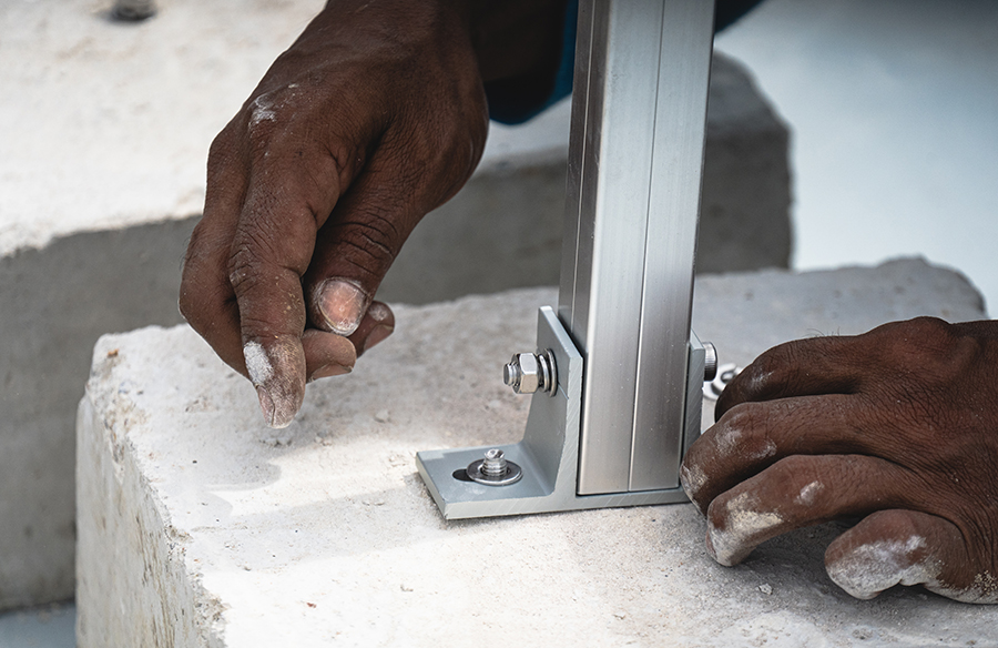
Architects often treat welded joints as lines on paper, yet each line defines strength, alignment, and long-term durability.
Every joint detail guides how fabricators assemble, inspect, and finish structural and ornamental work, from canopy frames to stair stringers.
Understanding how to specify weld types, symbols, and tolerances bridges design intent with fabrication reality, ensuring that what is drawn performs safely once built. Stick around to learn the basics.
 Choosing the Right Weld Type for Structural and Architectural Needs
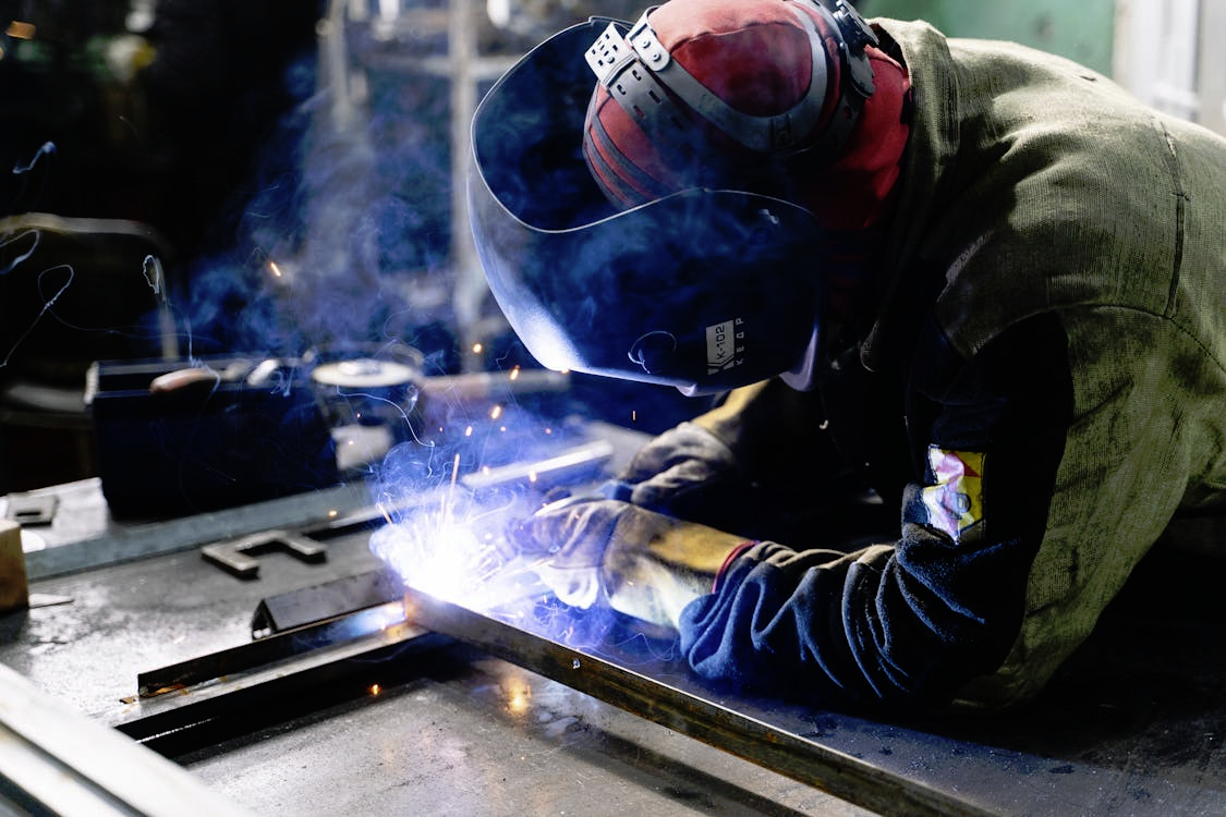
Selecting the right weld type begins with understanding how structure, appearance, and access shape the joint. Fillet, groove, and plug welds each serve distinct roles depending on load paths and visibility. A beam flange splice demands deep penetration, while a handrail post may rely on a clean, uniform fillet that blends with the finish.
Architects should reference AWS D1.1 and related codes to match the joint category to service conditions. In this context, completing Tidewater Tech’s combination welding trade school program can give design professionals insight into processes like GTAW, GMAW, FCAW, and SMAW, showing how each affects heat input and weld bead geometry.
It’s like choosing a brush for a painting, where the tool determines the texture. The more you understand the process behind the weld, the better your drawings anticipate what happens in the shop or field.
Applying AWS Welding Symbols Correctly on Drawings
Welding symbols act as a universal language between designers and fabricators. When placed correctly, they eliminate ambiguity about where the weld sits, its size, and its finish. A misplaced arrow or missing tail note can lead to costly rework once fabrication begins.
Architects should rely on AWS A2.4 as the reference for symbol standards. Each symbol communicates multiple details at once, such as weld type, contour, and whether the operation occurs in the shop or the field.
Including welding notes in the general sheet and repeating key symbols in enlarged details improves clarity. Coordinating these with the structural engineer’s set ensures consistency across disciplines, keeping inspectors and fabricators aligned on intent.
Managing Heat Distortion and Alignment in Metal Assemblies
Heat distortion can warp even the best-detailed assembly if joint sequence and restraint are ignored. When metal expands and contracts unevenly, members twist or pull out of alignment, turning a straight frame into a wave.
To control distortion, specify balanced welding from opposite sides, short intermittent welds when allowed, and cooling intervals for thick plate.
Architects can note preferred weld sequences in coordination with the fabricator, especially on exposed assemblies where visual straightness matters. Pre-setting parts with small offsets before welding can also counter expected movement.
Good communication between design and shop teams limits grinding and field correction later, keeping finishes intact and inspection reports clean. Thoughtful sequencing preserves both appearance and structural accuracy.
Specifying Finishes, Tolerances, and Visual Quality Standards
Finishes and tolerances determine how refined a welded assembly appears after installation. A structural frame may allow slight irregularities, but exposed architectural joints need tighter control of bead profile, grinding, and blending.
Specify whether welds are left as welded, ground smooth, or polished, and identify the finish sequence relative to painting or galvanizing.
Tolerance notes should reflect both the structural code and fabrication practicality. Overly tight limits increase cost without improving performance. Coordinate early with the fabricator to align expectations, and confirm inspection criteria so both parties judge quality the same way. Clear finish and tolerance language removes interpretation, keeping visual standards consistent from shop mock-up to field installation.
Coordinating Shop and Field Welding with Clear QC Documentation
Coordination between shop and field welding decides whether a project flows smoothly or stalls during inspection. Shop welds benefit from controlled conditions, while field welds face weather, limited access, and variable alignment.
Architects should indicate on drawings where each weld occurs, noting any sequences that affect fit-up or erection timing. A QC checklist helps track inspection points and verify that joint prep, root passes, and visual checks meet AWS criteria.
Regular review meetings between design, fabricator, and inspector reduce miscommunication. When everyone understands weld locations, inspection stages, and recordkeeping, the final structure meets both design intent and code requirements. Organized documentation keeps fabrication and field work aligned from start to finish.
Final Thoughts
Detailing welded joints links design vision with fabrication precision. Each note and symbol turns intent into measurable performance.
When architects understand process limits and inspection needs, welds become reliable, efficient, and visually consistent, joining craft and structure into one coherent design language.