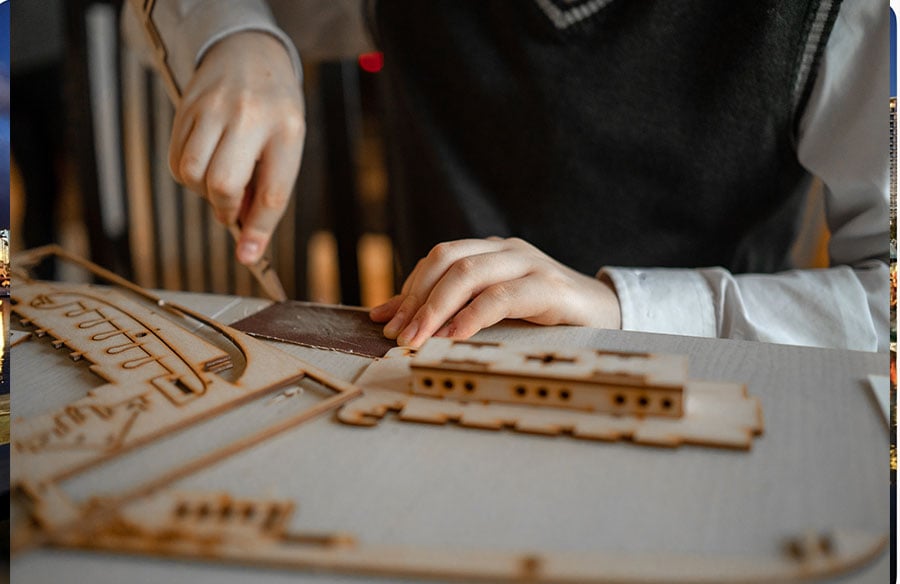
Physical models remain an important part of architectural design despite the widespread use of BIM, rendering, and real-time visualization. A model reveals massing, spatial relationships, facade proportions, and site conditions in ways that are difficult to judge on a flat screen. The challenge lies in translating increasingly complex digital drawings into physical components without losing dimensional consistency.
Laser cutting has become a common fabrication tool in architectural model making because it connects vector-based design files directly with sheet materials such as cardboard, MDF, plywood, and acrylic. Instead of measuring and trimming every component by hand, designers can prepare geometry digitally and reproduce walls, floor plates, screens, terrain layers, and structural elements with controlled dimensions.
The value of the process is not limited to speed. Its greater contribution lies in the relationship between digital design, fabrication constraints, material behavior, and physical assembly.
Role of Laser Cutting in Architectural Model Making
Precision and Repeatability
Scale changes magnify small fabrication errors. At 1:100, a one-millimeter deviation represents 100 mm in the actual building. Misaligned floor plates, irregular window openings, or inconsistent facade modules can therefore distort the visual reading of a model.
A laser cutter follows vector paths rather than manually marked cutting lines. Repeated components can be produced from the same geometry, which is useful for curtain-wall modules, louvers, columns, window frames, roof ribs, and repetitive structural grids.
Consistency becomes more important as the number of parts increases. A tower model containing dozens of identical floor plates, for example, is difficult to fabricate manually without gradual dimensional variation. Digitally controlled cutting keeps those layers aligned during assembly.
Complex Geometries and Parametric Patterns
Contemporary architecture often includes perforated facades, irregular grids, folded surfaces, and computationally generated patterns. Some of these forms contain hundreds of openings or repeated elements that would be impractical to cut individually with a knife.
Laser cutting converts such two-dimensional geometry into physical parts directly from CAD or vector files. Parametric screens, patterned cladding, diagrid structures, and layered landscape contours can therefore be represented without simplifying every feature into basic rectangles.
Fabrication limits still apply. A pattern that appears coherent on screen may contain bridges too narrow to survive at model scale. Digital complexity must therefore be adjusted to the thickness, strength, and thermal behavior of the chosen material.
Digital-to-Physical Workflow
CAD File Preparation
Good results begin before the material reaches the cutting bed. Files exported from AutoCAD, Rhino, Illustrator, or similar software should contain clean vector geometry with clearly defined cutting paths.
Duplicate lines are a common problem. When two vectors occupy the same position, the laser may travel over that path twice, increasing edge darkening and widening the cut. Open contours can create incomplete parts, while unnecessary construction geometry adds processing time and complicates file organization.
Line types should also be separated according to their purpose. Full cuts, engraved information, and light scoring lines normally require different machine settings. Clear layer management reduces mistakes during setup.
Scale Conversion and Detail Simplification
Reducing a full-size architectural drawing to 1:50 or 1:200 is not simply a matter of changing the scale factor.
Window mullions, handrails, facade joints, steel sections, and narrow openings may become too small to fabricate after reduction. A 20 mm architectural detail becomes only 0.2 mm at 1:100. Depending on the material and equipment, that feature may disappear completely or break during handling.
Model drawings therefore require selective simplification. Major proportions should remain accurate, while construction details that no longer communicate useful information can be enlarged, merged, or removed.
This editing stage separates a fabrication-ready model file from a reduced construction drawing.
Cutting, Engraving, and Scoring
Different laser operations can communicate different levels of architectural information.
CO₂ laser cutting machines are widely used in architectural model making because they can cut and engrave common non-metallic materials such as acrylic, MDF, plywood, paperboard, and cardboard.
Full-depth cutting defines walls, slabs, openings, roof profiles, and detachable components. Engraving adds surface information without separating the material. Brick courses, paving layouts, facade joints, road markings, roof lines, and room boundaries can be represented through shallow surface marks.
Scoring sits between those two operations. A light line may indicate a fold, alignment point, assembly reference, or material transition.
Used together, these operations reduce the number of separate pieces needed to communicate architectural detail.
Materials for Laser-Cut Architectural Models
Cardboard and Paperboard
Cardboard remains useful for conceptual and massing studies because it is inexpensive, lightweight, and easy to assemble. Floor plates, walls, site boundaries, and early facade studies can be produced quickly, which suits iterative design stages where geometry may change several times.
Material density matters. Very thin board can curl under heat, while loose fibrous surfaces may leave less defined edges. Test cuts are therefore worthwhile before processing a complete set of components.
MDF and Plywood
MDF is commonly used for site bases, walls, landscape contours, structural pieces, and presentation models. Its uniform composition produces predictable cuts and gives larger elements more rigidity than paper-based materials.
Plywood introduces a visible grain and layered edge structure. That appearance can become part of the model language, particularly in conceptual or structural studies.
Both materials can develop darkened cut edges. The effect may be acceptable in a working model, but exhibition pieces sometimes require sanding, painting, or surface finishing.
Acrylic
Transparent acrylic is widely used in architectural models to represent glazing, curtain walls, water features, and other transparent elements. Its clarity creates a strong visual distinction between solid building volumes and glazed surfaces without relying on additional graphic treatment.
For glazing panels, curtain-wall elements, and other transparent model components, acrylic laser cutting is commonly performed with CO₂ lasers, whose 10.6 μm wavelength is well absorbed by acrylic.
The process can produce smooth, well-defined edges without the cutting force associated with saws or blades. Thin frames, narrow mullions, and small transparent parts still require careful handling, as slender connections can fracture during removal or assembly.
Key Fabrication Considerations
Kerf Compensation
A laser does not create a line with zero width. Material is removed along the toolpath, producing a narrow cut known as kerf.
That loss becomes important when parts must interlock. If a tab and slot are drawn at exactly the same nominal dimension, the final fit may be too loose or too tight once the kerf is considered.
Compensation should be based on actual test pieces rather than a universal value. Material type, thickness, beam focus, power, and cutting speed all influence the result.
For models containing friction-fit joints, small calibration samples can prevent extensive rework later.
Minimum Feature Size
Fine geometry requires more than dimensional accuracy. It also needs enough material to remain structurally intact.
Perforated screens illustrate the problem clearly. When openings are placed too close together, the remaining bridges may char, warp, detach, or fracture during assembly. Similar issues occur with miniature mullions, railings, truss members, and decorative patterns.
Minimum feature size should therefore be judged against both cutting capability and post-cut handling. A component that survives fabrication but breaks during assembly is still poorly designed.
Material Thickness and Joint Tolerances
Sheet thickness affects appearance, stability, and assembly logic.
A thick wall may look oversized at 1:200 even if it is easier to handle. Conversely, very thin board can represent the correct visual proportion but lack enough stiffness to remain straight.
Joint dimensions also need to correspond with the actual sheet thickness rather than the value printed on the product label. Nominal 3 mm material, for example, may measure slightly above or below that figure.
Measuring the sheet before preparing slot geometry reduces fit problems across a large model.
Architectural Model Applications
Facade and Screen Models
Facade studies benefit strongly from laser-cut fabrication because elevation geometry is predominantly planar. Perforated panels, shading screens, curtain-wall grids, fins, balcony patterns, and repeated openings can be tested at several scales.
Physical models are also useful for examining transparency and shadow. A screen pattern that looks balanced in elevation may appear too dense once placed in front of a building volume.
Topographic and Site Models
Contour models translate digital elevation data into stacked layers. Each contour can be cut from board, plywood, or another sheet material before the layers are aligned to reconstruct the terrain.
This approach works well for sloping sites, landscape studies, campus plans, and projects where the relationship between building form and ground level is central to the design.
Reference holes or alignment marks can simplify stacking when dozens of contour layers are involved.
Structural and Urban Models
Trusses, frames, gridshell components, and repetitive structural systems can be represented as flat-cut pieces assembled into three-dimensional configurations.
At the opposite scale, urban models use the same process for building footprints, street networks, blocks, plot boundaries, and masterplan elements. Repetition becomes an advantage here: hundreds of basic components can be derived from organized digital geometry rather than measured separately.
Laser Cutting vs Other Model-Making Methods
Hand Cutting
Manual fabrication remains valuable during early concept development. A knife, ruler, and board may be faster when only a few simple volumes are required.
Hand cutting also encourages direct material experimentation. Designers can modify a wall, remove a volume, or alter an opening without returning to the computer.
Its limitations become more visible when geometry grows repetitive, highly detailed, or dimensionally dependent.
3D Printing
Laser cutting works primarily through planar components assembled into three-dimensional form. 3D printing approaches the problem differently by building volumetric geometry layer by layer.
Organic forms, complex curved surfaces, sculptures, and intricate solid components may therefore be better candidates for additive manufacturing.
Many architectural models combine both techniques. Laser-cut sheets can form walls, floors, terrain, and facade systems, while printed parts represent curved roofs, complex joints, or irregular objects.
The choice should follow geometry rather than technology preference.
Common Fabrication Errors
Over-Detailed Geometry
Excessive detail is one of the most frequent problems in architectural model files. Features copied directly from construction drawings may become visually insignificant or physically impossible after scaling.
Simplification usually produces a clearer model than attempting to preserve every line.
Duplicate Cutting Paths
Overlapping vectors can cause repeated passes, burnt edges, and unnecessary processing. File cleanup should therefore include a check for duplicate lines, hidden geometry, and stacked objects before export.
Poor Assembly Planning
Parts should not be designed independently of the sequence in which they will be joined.
A facade panel may fit dimensionally but become impossible to insert after adjacent walls are glued. Internal floors can obstruct later structural elements. Tabs may become inaccessible once an enclosure is closed.
Numbering parts, adding discreet alignment marks, and testing the assembly order digitally can prevent these problems.
Laser Cutting in the Architectural Design Workflow
Rapid Design Iteration
A physical model does more than present a finished proposal. When fabrication files remain linked to the digital design process, geometry can be revised, recut, and compared between iterations.
Changes to facade density, building mass, circulation, floor relationships, or site geometry can therefore be evaluated physically without rebuilding the entire model by hand.
Physical Model Evaluation
Screens reveal dimensions; models reveal relationships.
A laser-cut model can expose awkward proportions, excessive facade density, weak spatial transitions, or unresolved connections that may not be obvious in renderings. Light passing through perforated panels can also reveal how an elevation behaves as a three-dimensional surface rather than a flat graphic.
For this reason, laser cutting in architectural model making is most useful when treated as part of design development rather than a final presentation technique. The machine translates geometry, but the architectural value comes from what designers learn once that geometry exists as a physical object.