
A fabricator of custom architectural facades in Los Angeles was contracted to produce 3,200 perforated aluminum and stainless steel panels for a 40-story commercial tower. The panels, each up to 3 meters × 1.5 meters in size and 2.0 mm thick, required edge straightness within ±0.2 mm across the full length to achieve a seamless, joint-free appearance on the building’s exterior. The company’s existing plasma cutting table could not hold this tolerance. Thermal distortion from the plasma arc produced edge waviness of 0.5–1.0 mm, and the oxidized cut edge required extensive manual grinding. Panels that passed shop inspection still required on-site trimming and shimming during installation, adding an average of 4 hours of field labor per panel. The scrap rate on these micro-tolerance panels was 18%.
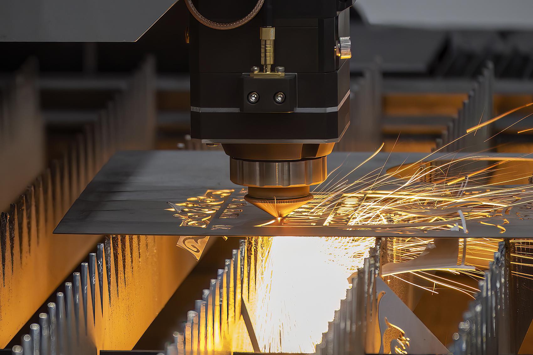
The company replaced the plasma table with a YIHAI LASER YC-1530 precision sheet metal laser cutting machine equipped with a 4 kW single-mode fiber laser, nitrogen assist, and a Raytools XC3000S cutting head with capacitive height sensing and collision protection. The machine’s precision motion system delivered cut-edge linearity of ±0.03 mm per meter and a kerf width of 0.15 mm. Thermal distortion was eliminated; panels emerged flat to within 0.1 mm across the full diagonal. The scrap rate dropped to 0.8%, on-site rework was virtually eliminated, and total project cost fell by 35% compared to the plasma-based estimate.
The Pre-Upgrade Baseline: Plasma Cutting of Large-Format Architectural Panels
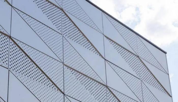 The architectural panel contract required cutting 3,200 panels from 2.0 mm 5052-H32 aluminum and 1.5 mm 316 stainless steel. Each panel had a complex outer profile with interlocking edges designed to mate with adjacent panels with a nominal joint gap of 1.0 mm ±0.3 mm. The gap had to be uniform along the entire perimeter; any deviation beyond 0.3 mm would be visible from street level and would require on-site correction.
The existing plasma cutting table used a 60 A air plasma torch. On 2.0 mm aluminum, cutting speed was 1.2 m/min with a kerf width of 2.5–3.0 mm. The plasma arc deposited approximately 2,800 J/mm into the cut zone, producing a heat-affected zone 4–6 mm wide. The differential thermal expansion caused the large, thin panels to warp. Post-cut flatness deviation averaged 1.5 mm, and edge straightness (deviation from a true line) was 0.5–1.0 mm along the 3-meter length.
The post-plasma process sequence included:
- Slag removal: A needle scaler and angle grinder removed dross from the bottom edge. Time: 18 minutes per panel.
- Edge grinding: The oxidized, rough plasma-cut edge was ground to bright metal using a linear edge sander to improve straightness. Time: 22 minutes per panel.
- Straightening: Warped panels were flattened on a 150-ton hydraulic press. Time: 8 minutes per panel (applied to all panels).
Even after grinding, edge straightness could not be reliably brought within ±0.2 mm because the plasma kerf was inherently irregular. Panels that failed QC inspection (18%) were scrapped and re-cut. The 18% scrap rate represented 576 panels over the project, each costing $140 in material and machine time. Panels that passed shop inspection still exhibited minor edge waviness that required on-site adjustment. The installation crew averaged 4 hours of shimming, trimming, and re-drilling per panel to achieve an acceptable joint gap. At a field labor rate of $85 per hour, this added $340 per panel in installation cost.
Project cost estimate (pre-upgrade, based on actual performance during the first 200 panels):
| Cost Element | Per Panel | Total (3,200 panels) |
|---|---|---|
| Plasma cutting (machine time + labor) | $18 | $57,600 |
| Slag removal labor (18 min × $28/hr) | $8.40 | $26,880 |
| Edge grinding labor (22 min × $28/hr) | $10.27 | $32,864 |
| Straightening labor (8 min × $28/hr) | $3.73 | $11,936 |
| Scrap material & re-cut cost (18% × $140) | $25.20 | $80,640 |
| On-site installation rework (4 hrs × $85/hr) | $340.00 | $1,088,000 |
| Total Project Cost (cutting through installation) | $405.60 | $1,297,920 |
The on-site rework dominated the total cost. The fabricator was losing $340 per panel on installation, and the project was on track to exceed its bid by over $400,000. The plasma process was incapable of meeting the micro-tolerance requirement.
Selection Criteria
The fabricator evaluated two alternatives: a waterjet cutting machine and a precision fiber laser cutting machine. The selection criteria were:
- Edge straightness of ±0.1 mm per meter, stable across a 3-meter cut length. Required to achieve the interlocking joint tolerance.
- Kerf width ≤0.2 mm and no thermal distortion on 2.0 mm aluminum and 1.5 mm stainless steel.
- Production throughput of at least 8 panels per 8-hour shift to meet the project schedule.
- Reliable height sensing on large, thin sheets that may flex under their own weight during cutting.
Waterjet was rejected because the abrasive-laden water jet produced a kerf of 0.8–1.2 mm—too wide for the tight joint tolerance—and the abrasive slurry introduced a waste disposal problem. The YIHAI LASER YC-1530 precision sheet metal laser cutting machine was selected. It integrated a 4 kW single-mode fiber laser source (IPG YLR-4000), a Raytools XC3000S cutting head with integrated capacitive height sensing and ±0.01 mm positioning repeatability, and a CypCut Pro 6000 CNC controller. The machine’s gantry used direct-drive linear motors on the X and Y axes with 0.1 µm resolution linear encoders, enabling the required edge straightness. The machine shipped with a preloaded parameter library for 2.0 mm aluminum and 1.5 mm stainless steel, including nitrogen-assisted cutting schedules optimized for edge quality.
The New Process: Precision Fiber Laser Cutting with Nitrogen Assist
 The YIHAI LASER machine was installed in February 2026. The cutting parameters for the two panel materials were loaded directly from the controller’s parameter library:
Cutting parameters: old vs. new process
| Parameter | Plasma (Old) | YIHAI LASER 4 kW Fiber Laser (New) |
|---|---|---|
| Cutting speed (2.0 mm Al) | 1.2 m/min | 28 m/min |
| Cutting speed (1.5 mm SS) | 0.8 m/min | 22 m/min |
| Assist gas | Air (plasma) | Nitrogen (99.995%) |
| Kerf width | 2.5–3.0 mm | 0.15–0.18 mm |
| Edge straightness (over 3 m length) | ±0.5–1.0 mm | ±0.03 mm |
| Flatness deviation after cutting | 1.5 mm avg. | 0.08 mm avg. |
| Heat-affected zone width | 4–6 mm | 0.3–0.5 mm |
| Edge condition | Oxidized, rough, dross | Bright, smooth, dross-free |
| Post-cut grinding required? | Yes (22 min/panel) | No |
| Straightening required? | Yes (8 min/panel) | No |
The nitrogen assist gas at 14 bar produced a clean, oxide-free edge on both aluminum and stainless steel. The cutting speed of 28 m/min on aluminum reduced the heat input per unit length by a factor of approximately 100 relative to plasma, eliminating thermal distortion entirely. The machine’s capacitive height sensor, sampling at 1 kHz with a filter time constant optimized for thin sheet, maintained a constant 0.8 mm standoff across the full panel surface, preventing nozzle collisions even when the large sheet vibrated during rapid traverses.
The CypCut controller’s precision motion algorithm maintained constant velocity through corners and small radii, producing uniform edge quality along the interlocking features. The laser also etched a unique panel ID and alignment marks onto each part, eliminating manual marking and reducing installation errors.
Implementation and Operator Transition
The YIHAI LASER machine arrived with a preloaded parameter library including the specific 2.0 mm aluminum and 1.5 mm stainless steel cutting schedules required for the project. The fabricator’s plasma operator and a newly hired technician completed a four-day training program with a YIHAI LASER application engineer. The training covered machine startup, parameter selection from the CypCut touchscreen, nozzle inspection and replacement, and quality inspection using a calibrated straightedge and feeler gauge.
The Raytools capacitive height sensor required no manual calibration after the initial setup; it auto-calibrated at the start of each sheet and maintained constant standoff throughout the cut. The machine’s sealed beam path and factory-aligned collimator eliminated the need for on-site optical alignment, a significant time-saver compared to the fabricator’s previous experience with a CO₂ laser on another line.
The architecture firm’s quality inspector visited the shop after the first 100 laser-cut panels were produced. Using a coordinate measuring arm, they confirmed that edge straightness across a 3-meter panel was consistently within ±0.04 mm, and the joint gap between adjacent panels assembled on a mock-up frame was 1.0 mm ±0.1 mm. The mock-up was approved without modification. This approval, which had taken three iterations under the plasma process, was achieved on the first submission.
Conclusion
Architectural metal facades with interlocking, micro-tolerance joints are not possible with plasma cutting. The thermal distortion and kerf irregularity inherent to the process drive rework costs that exceed the bid price. The fabricator’s investment in a YIHAI LASER precision sheet metal laser cutting machine with a 4 kW single-mode fiber laser and a direct-drive gantry system eliminated these variables. Edge straightness improved from ±0.5 mm to ±0.03 mm, the scrap rate fell from 18% to under 1%, and on-site installation rework was virtually eliminated. On a single project of 3,200 panels, the laser saved over $1.1 million relative to the plasma baseline, paying back the $132,000 machine cost within three weeks. For architectural fabricators bidding on high-tolerance facade work, a precision fiber laser cutting machine is not a discretionary purchase; it is a prerequisite for contract compliance and positive project margin.