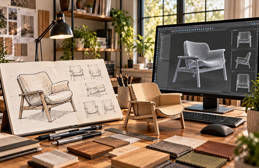
Every furniture designer has made a prototype that taught one lesson: the seat was four centimetres too deep. A day of cutting and glueing, a trip to a workshop, a few hundred in materials, and the answer was in the first minute of sitting on it. A good 3D workflow does not remove prototypes. It moves most of those lessons to the screen, where changing four centimetres takes seconds.
This article follows a piece of furniture from a loose sketch to files a workshop can use, and shows where the iteration really happens.
Start from a sketch that asks one question
A sketch is not a specification. It is a question: what if the back leaned like this, what if the arm met the seat at that angle. Before opening any software, write down what the model needs to answer. Is it overall proportion? Comfort? Whether two materials sit well together?
That discipline shapes the whole model. A designer who wants to test proportions can build a rough massing in an hour. One who wants to test joinery needs far more detail in a smaller area. Modelling everything to the same level on the first pass is a common time sink.
Block the form, then judge it in context
The first model should be crude and dimensionally honest. Block out the seat height, depth, back angle and overall footprint using real numbers, not “about right”. Then look at it from the angles a person would see it: from the doorway, from a sitting position, from above.
Placing the model in a simple room, even a grey box with a door and a window, does more than any amount of staring at it in isolation. Scale mistakes show up at once. A console that looked elegant alone looks stranded against a long wall. This is also the quickest point to compare variations: three leg heights, two back angles, a shallower arm. Save each as a variant and review them side by side.
Test joinery on the screen before cutting anything
Once the form is settled, the model starts to carry construction. Parts are separated, thicknesses are set, and joints are drawn: a mortise and tenon, a dowel, a bolted bracket, a corner block. This is where a 3D model earns most of its keep, because collisions show up that a sketch hides.
Two rails want to occupy the same space at the corner. A drawer cannot open because the leg is in the way. A seat frame needs a clearance gap, but the upholstery thickness has not been counted. In a physical prototype each of these costs a failed attempt. In a model, a clash simply shows and gets fixed.
It also helps to model the tolerances the workshop will need to handle: a reveal between a door and its frame, an expansion gap in a solid timber top, a cushion that compresses. Those small allowances keep the drawings honest.
Assign real materials and check the finish
After the structure, apply the materials: species of timber, veneer on a substrate, powder-coated or brushed metal, fabric weights. A model with materials applied can answer questions that a clay-style form cannot. Does the dark metal frame disappear against a dark floor? Does the pale oak look washed out beside a cream wall?
At this stage, a render of the model is useful as a decision tool and can be shown to clients or collaborators. It also gives a place to check whether the finish is realistic to produce. A sharp, thin edge in the model may not survive a real veneer wrap; a very pale lacquer may need extra coats that change the price.
Carry the model through to production
The mistake many designers make is to treat the model as a presentation asset and then start again when it is time to build. The better habit is to treat it as the single source for everything that follows.
Once the form is settled, the same model can feed furniture CAD models with 2D shop drawings for the workshop, so nothing is redrawn from scratch. The plan, elevation and section views come from the model, which means a change made once appears everywhere. Dimensions on the drawings cannot drift from the geometry the client approved, because they are the same geometry.
Check that the model is built the way the drawings will need. Parts should be named sensibly, thicknesses should match stock sizes, and components that repeat, such as four identical legs, should be one component used four times. Models that were only built to look good often need rebuilding at this point, which is the very rework the process was meant to avoid.
Keep the file tidy so the model survives handover
A model built over several weeks of experiments is usually untidy. Hidden construction lines, abandoned variants, parts with names like “copy 7” and layers that nobody remembers creating all slow down the next person who opens it, who may be you in six months.
Before the model leaves your hands, spend an hour on housekeeping. Delete or archive discarded variants. Name every part for what it is, such as “rear rail” or “left side panel”, and not by its position in the file. Group components by assembly. Check that mirrored or repeated parts are true copies, so a correction to one reaches all of them.
Keep a simple version log. A line for each saved milestone, saying what changed and why, lets you step back when a client prefers the earlier arm profile after all. Save milestones under dated names and never overwrite the approved version.
Finally, record the units and the origin point. A model drawn in millimetres and opened in inches is a classic source of nonsense, and a workshop that cannot tell where the zero point sits has to guess. These details are dull, and they decide whether the file can be reused or has to be redrawn.
When the workshop uses CNC
If the pieces are cut on a CNC router, the model also feeds the machine. Flat parts, such as panels, shelves and curved rails, are nested into sheet layouts and exported as 2D profiles, and the workshop converts those to toolpaths.
This is where file preparation matters. Ask the workshop which formats it accepts, how it wants layers organised, and whether it needs hole positions, pocket depths or edge profiles on separate layers. A studio that prepares CNC-ready DXF and NC files can hand over parts the machine can read without anyone cleaning up the geometry first. The tolerance and the tool diameter are things to agree before cutting, because an internal corner cannot be sharper than the cutter that makes it.
It is always worth cutting one test part, or one part in cheap material, before running a full sheet. Even a perfect model cannot show what a particular board does when it is machined.
When to still build a physical prototype
A model replaces many prototypes, but not all. Comfort is the main exception. A chair that measures correctly can still feel wrong, and only a full-scale mock-up reveals it. A cardboard or foam prototype made from the model’s printed outlines is cheap and fast, and it should be the last check before material is ordered.
Joints under load are the other exception. A render of a slender leg looks fine whether or not it can hold a person. Structural judgment comes from the maker’s experience, from a test piece, or from an engineer, not from the picture.
Conclusion: faster iteration, fewer surprises
A 3D workflow does not make design effortless. It changes where the effort goes. Cheap questions of proportion, clearance, finish and joinery are answered on the screen, in minutes. Expensive questions of comfort and strength are saved for one carefully chosen prototype.
The process that works is simple. Sketch with a question, block the form with real numbers, test the joinery, apply honest materials, and let the same model produce the drawings and cutting files. Build one physical mock-up at the end and not five along the way. Designers who work this way arrive at the workshop with fewer revisions, and the workshop notices.